A few months ago I posted about a project I was working on whose primary goal was to drive single-pixel drawing on a 16×2 character display. Of course the real goal of the project was just to move forward with electronics, trying new things in both software and hardware.
Where Were We?
When last we left the project, I had just realized that my plan to draw (persistent) pixels on the entire 16×2 display wouldn’t work with the LiquidCrystal library’s 8-custom-character limit. Here is a very abbreviated version of the 4 possible next-steps I set out for the project:
- Make the drawing grid 2×4 instead of 2×16, just to get the persistent drawing working. Add as much physical “bling” to the project as possible just to play with new stuff and multiple components updating in the loop.
- Investigate overcoming the 8-custom-character limit inside the LiquidCrystal library.
- If needed, investigate bypassing the LiquidCrystal library entirely to bypass the custom-character limit.
- Investigate methods for circuit documentation, using this project as the guinea pig (emphasis on versionable files and multi-platform support)
Goals 2 & 3: Getting More Than 8 Custom Chars
The easiest thing to discuss is what didn’t work out. I never spent any time looking into #2 or #3, but a commentor on the previous post left a link to an Arduino forum post that implied that 8-custom-character limit is due to the hardware itself, not the library. That link, plus a little more googling, leads me to believe this isn’t a path worth walking down right now.
Goal 1: Multi-Pixel Drawing
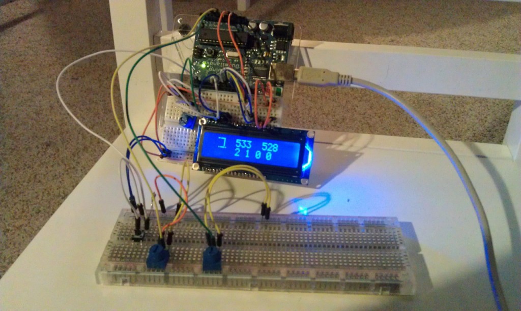
I did decide that my itch for this project wouldn’t be properly scratched until I had persistent, multi-pixel drawing working. By this I mean that you have a cursor of one pixel, and anywhere you move that cursor lights up and stays lit (unlike the last version, where the pixel could travel anywhere, but they didn’t stay lit). I was able to get this implemented without too much pain. Actually, the vast majority of the time I spent on this was debugging a hardware issue outside of my control that I didn’t have enough experience to recognize at first (quicky blog post later on that).
Also while working on this I added a clear button to the circuit and some positioning debug information to the display.
Goal 4: Documenting Circuits
I looked at a few different solutions. I knew the name Eagle as it gets thrown around all the time. I downloaded the free version and couldn’t even figure out how to draw on it. Granted, I didn’t spend much time on it because I didn’t think it was going to be the right solution, but still…
I considered a few more-generic layout tools like dia, Graffle, or Visio, but none of them felt right. I didn’t really want to use an X11 server on Mac OS X, which I would need for dia, and the others aren’t cross-platform. I think I tried a few others whose names I can’t remember, but none of them felt right.
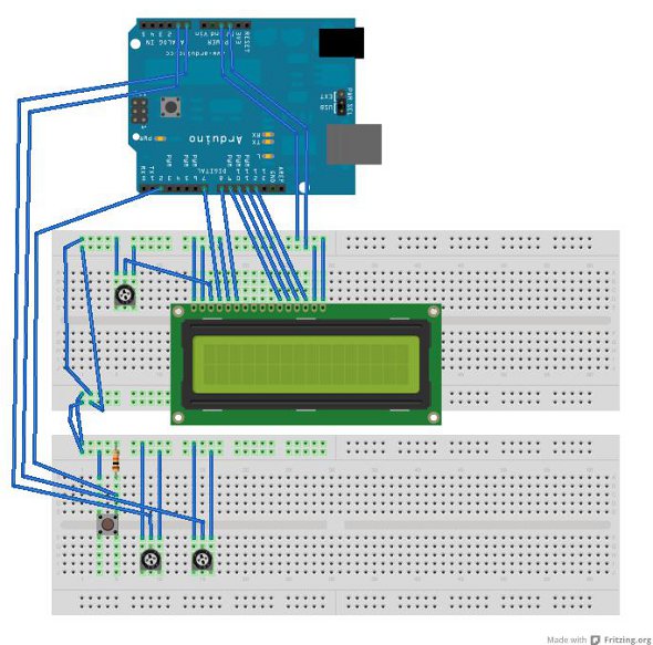
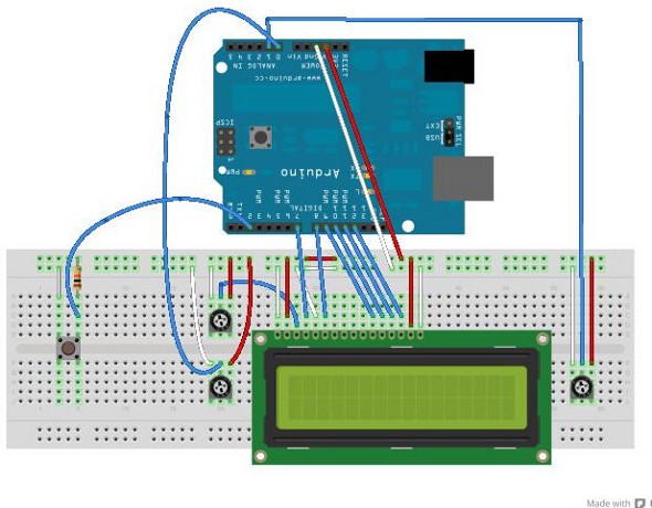
I had basically deferred this goal when, while looking at the Arduino docs and sample, I noticed they were made with Fritzing. I downloaded it and it was exactly what I was looking for. It saves in versionable XML, it’s very easy to lay out circuits, and it’s available for all three major desktop OSs. I get the impression that, if I were an experience EE I would feel limited by Fritzing and prefer something like Eagle, but at my current skill level I’m happy to grow with the still-young Fritzing.
Now What?
Here are my new goals:
- More bling! My current ideas are a new button which changes between three modes (draw, erase, and invert); one or more LEDs which indicate the mode (which will possibly also be drawn on the extra parts of the display); and, more maximum bling, a piezo which clicks when the cursor moves. Shouldn’t be too hard to bang out now.
- I want to be done with this project. To me that meant having the circuit documented, which is now done. Also, I couldn’t just (easily) ditch the breadboard and use another because my only Arduino is physically attached to one of the two breadboards I was using. Toward this end I re-did the project last night using only one breadboard. This will allow me to just set the breadboard aside after accomplishing #1 above, though to be honest I think I’ll be done with this entirely at that point. Love having it documented though. Frankly, having the circuit in Fritzing was a large reason why I felt comfortable changing the layout to just one breadboard – I knew I had reference if I made a mistake
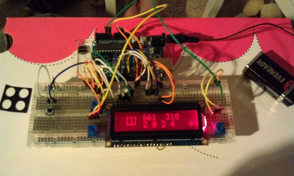
Here’s what the project looks like right now after being consolidated to a single breadboard:

Woo! I didn't change LCDs, that model supports RGB backlighting and I just wired it up to the red pin instead of the blue pin for a change.
Onward!


